 The stabilizer and the wing/fuselage junction
The stabilizer
Slightly enlarged compared to the real glider, the stabilizer has a volume greater than 0.5 for aerobatics. It is in one piece to be full-flying for radical deflections (2x90°) hoping to perform flips.
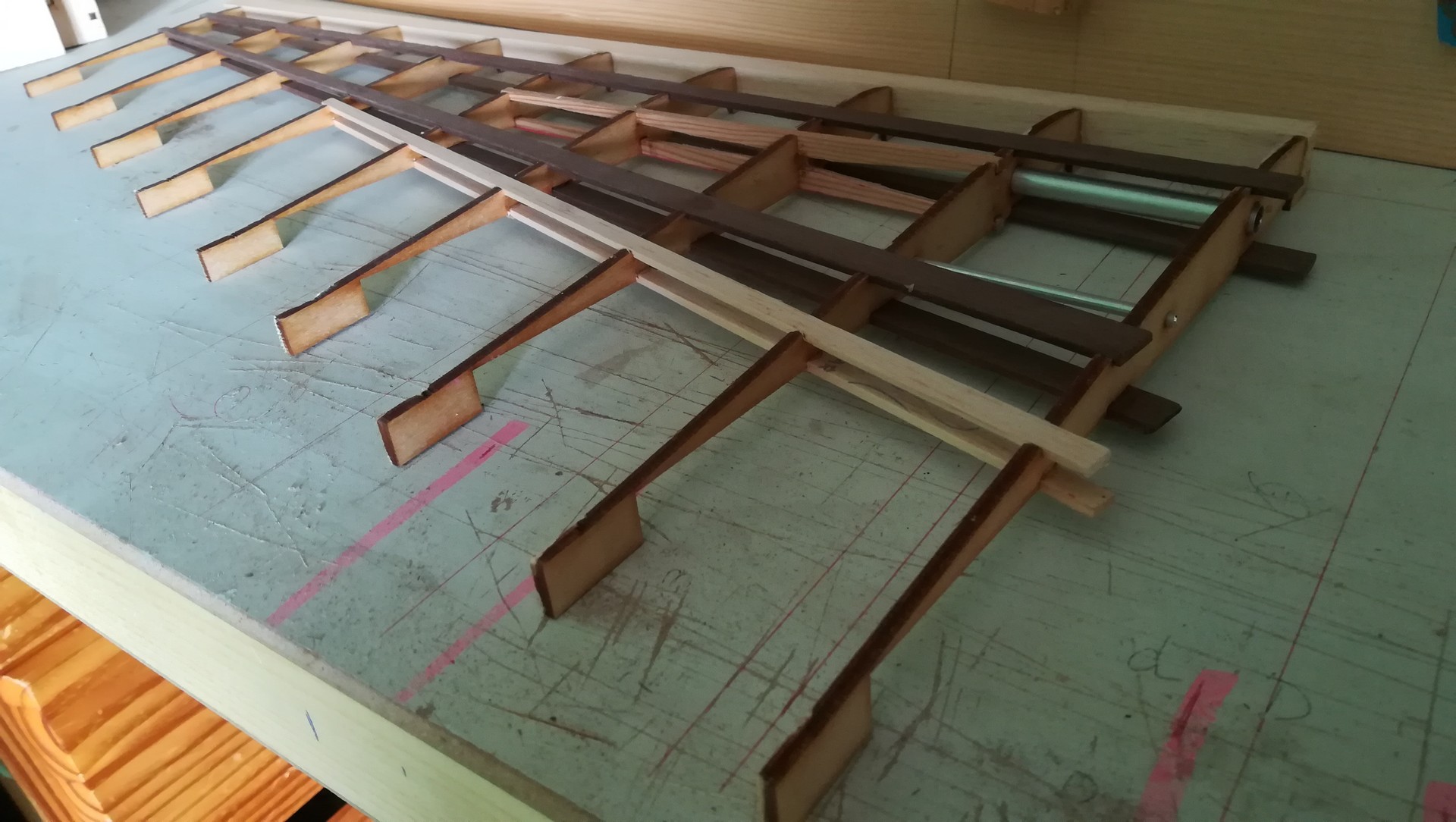
TP42, 9.3% at root, 6.8% at wingtip. The idea is to stay quite thin, and to refine by going to the wingtip. To avoid tail stalls that I seem to have sometimes spotted at the top of tight loops on my gliders.
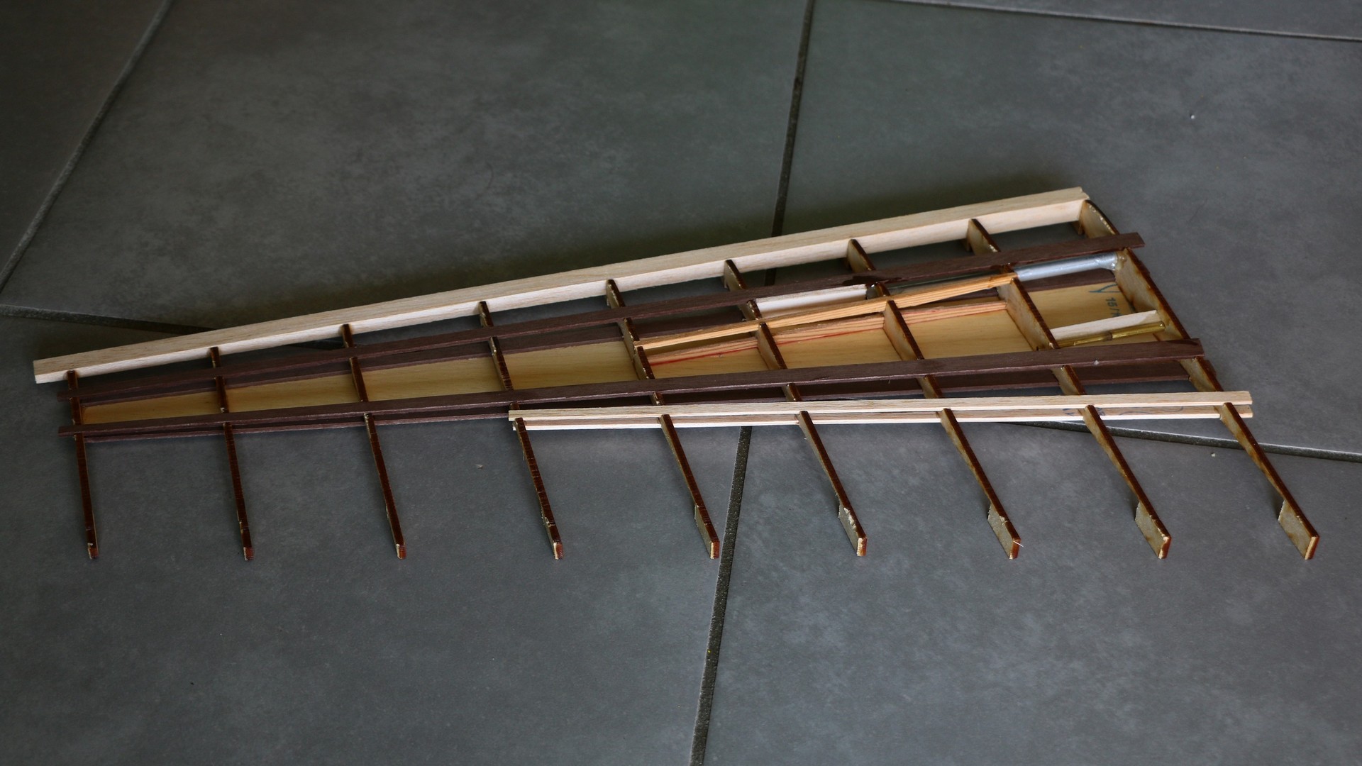
V-shaped spars are positioned at the end of the joiner metallic tube, to distribute the flexion in the wood structure.
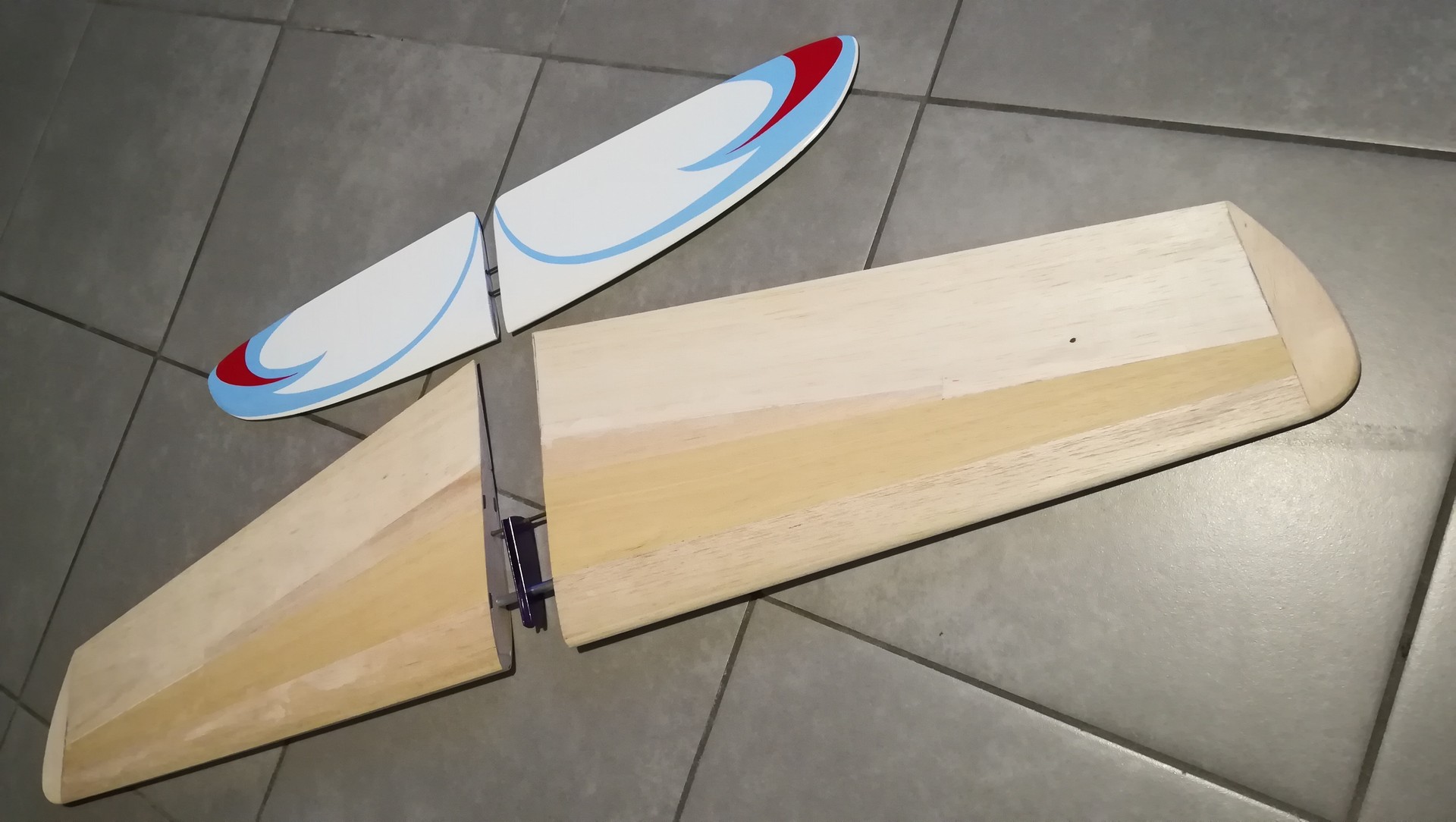
1m04 wingspan, next to the stabilizer of the Svolazzo. Skin 15/10, samba in the center and balsa around.
The wing/fuselage junction
This area required a bit of work. Scan and draw the original frames, then modify the karman ears to match the new airfoil SC17. I also chose to create 2 strong pieces to place the wing joiner with good load diffusion in fuselage.
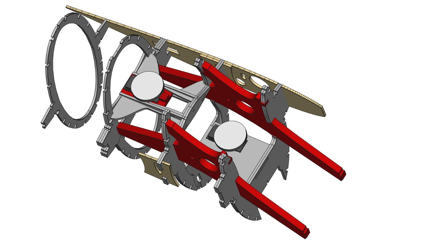
The strong piece (in red) is linked to 4 frames - instead of the original 2.
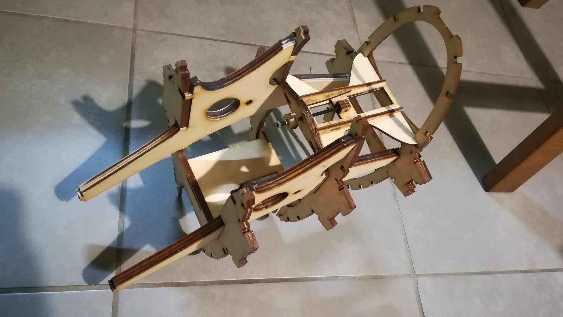
First assembly upon receipt of the cut parts by CDDesign.
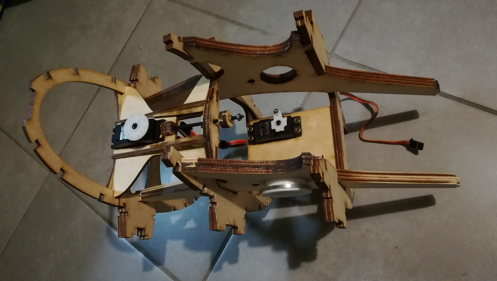
With servos.
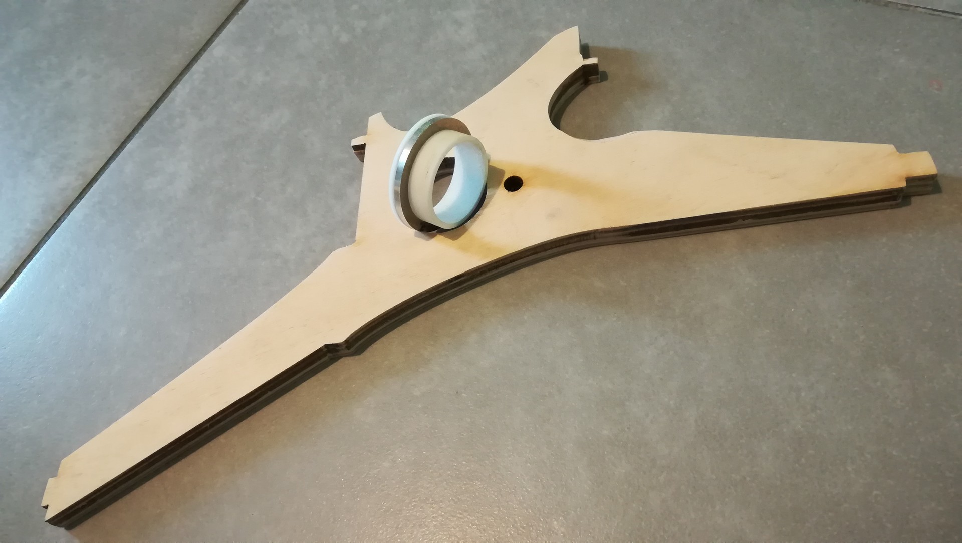
Thanks to my dad for the lathe machining of Teflon and aluminum rings to make junction with the wing joiner in the strong parts.
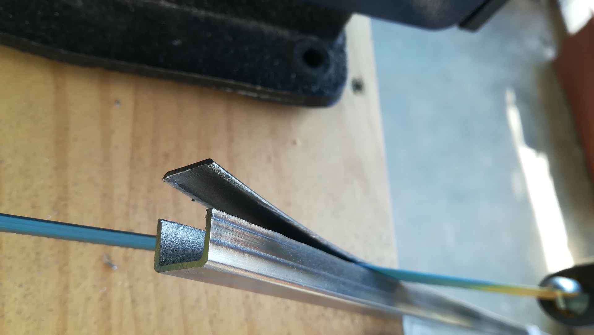
A square of steel is transformed into a U.
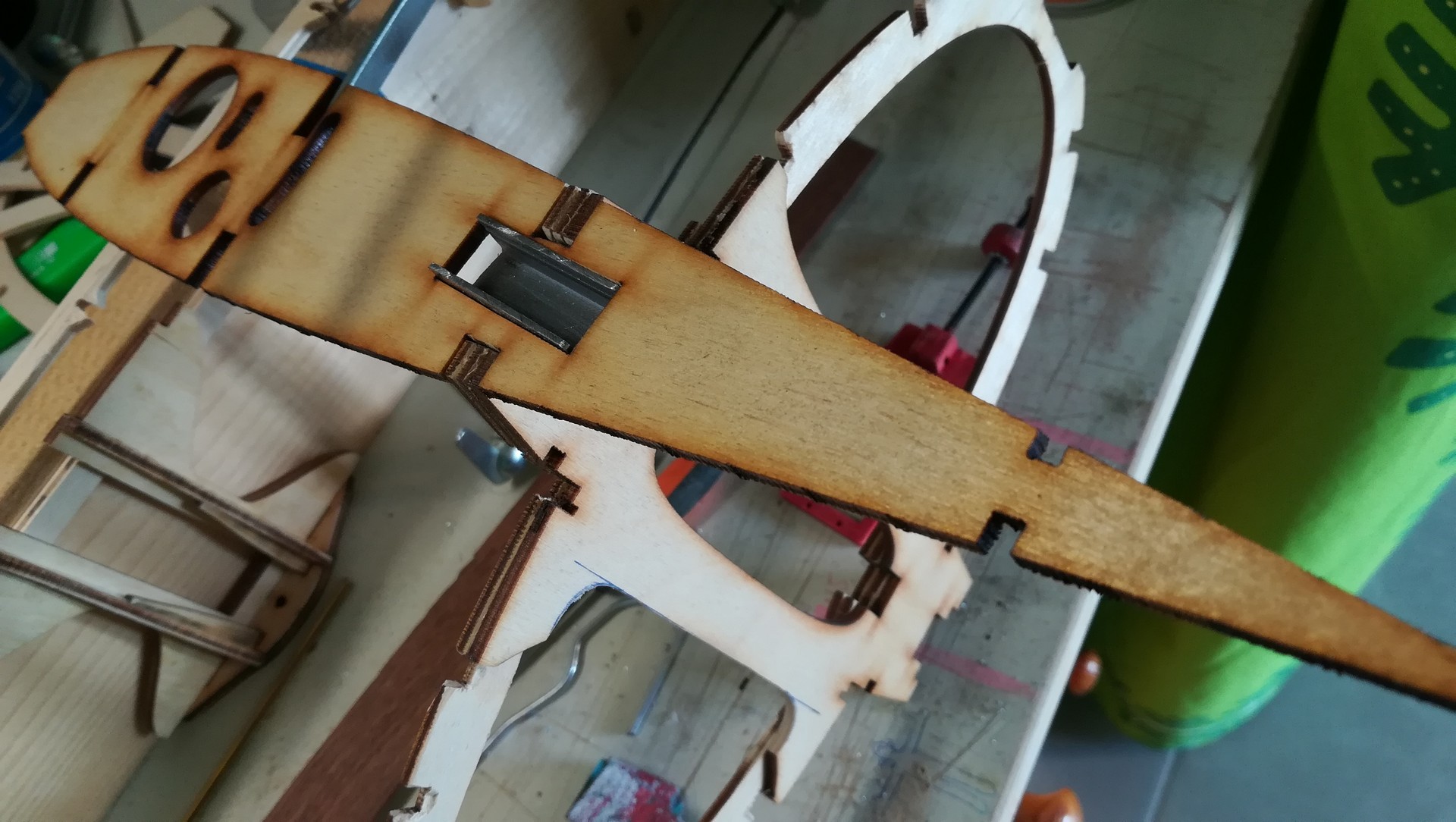
In the karman ribs and a strong frame, the steel U will receive a Teflon rectangle mounted on the incidence servos, which will be housed in the wings.
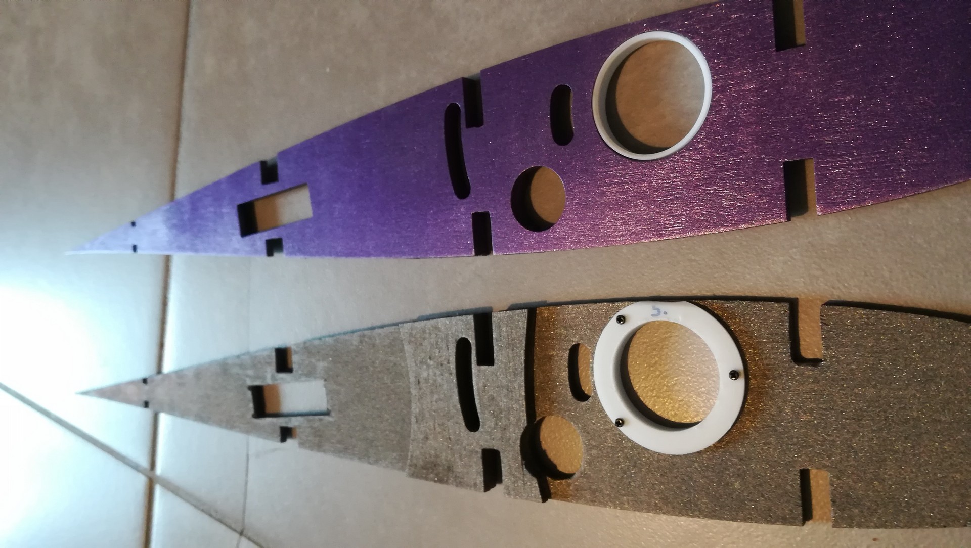
The ribs of karman receive Teflon rings which have a larger diameter than the wing joiner. The goal being that the loads diffuse in the strong parts, not in the karmans.